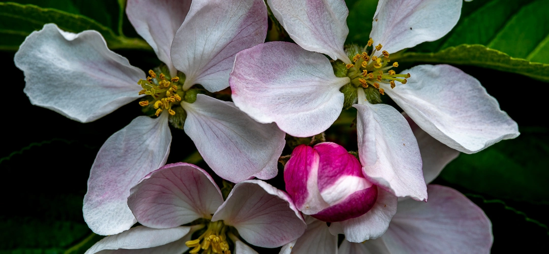
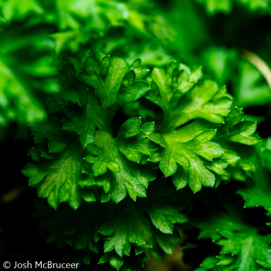
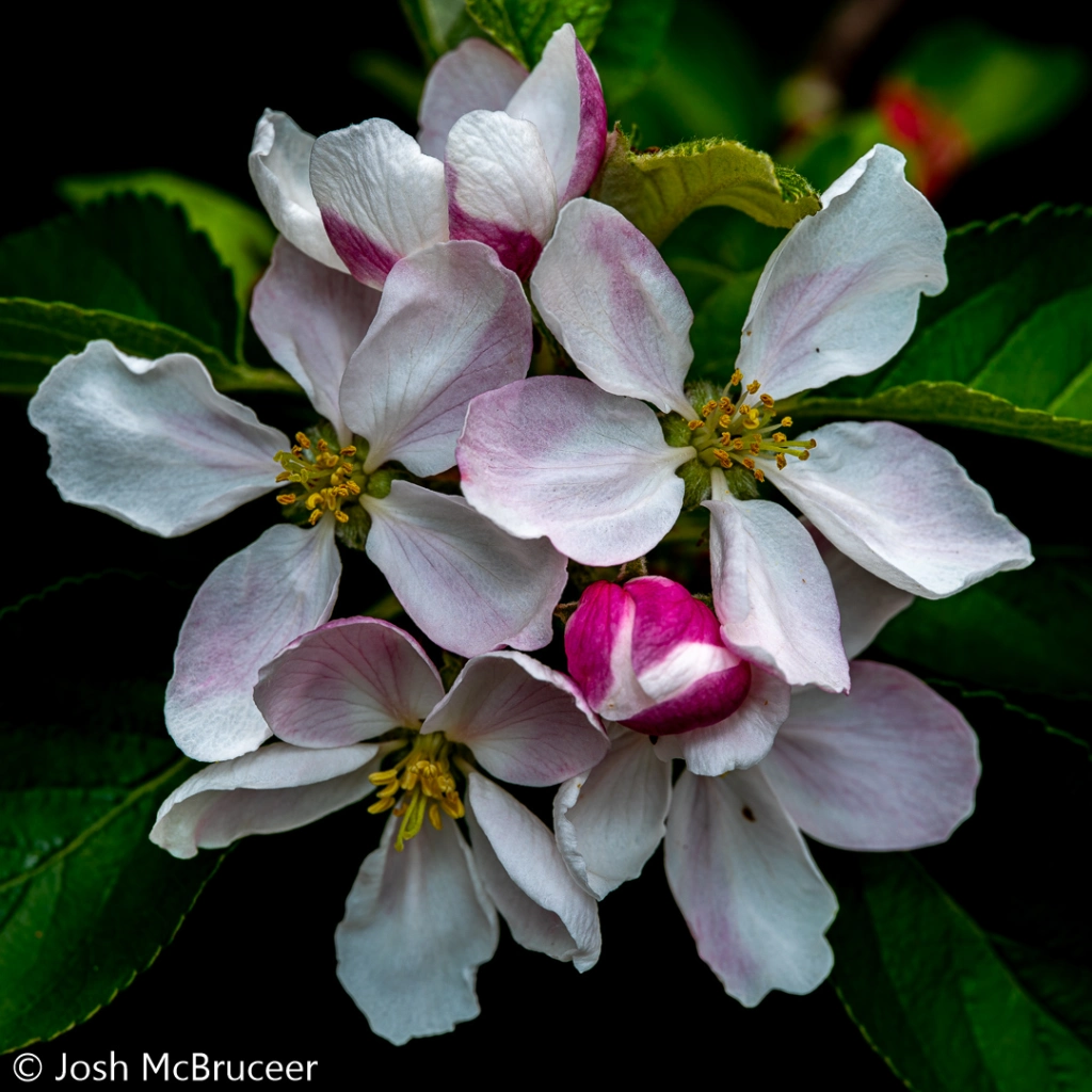
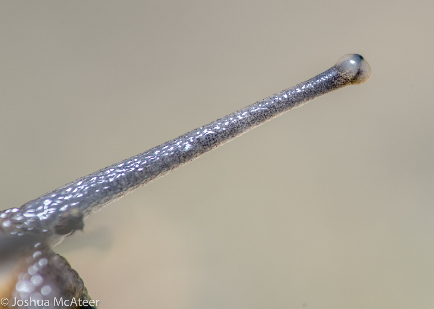
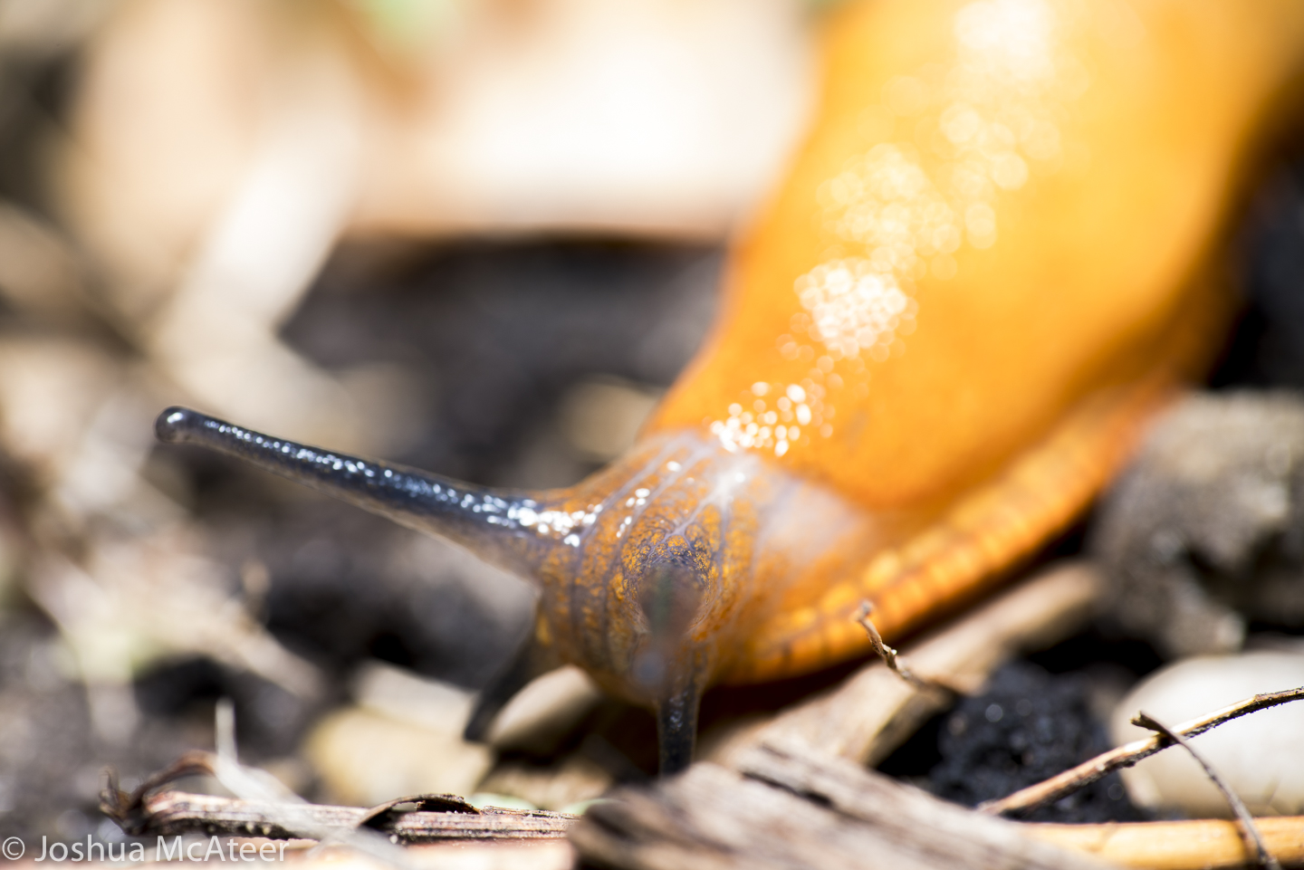
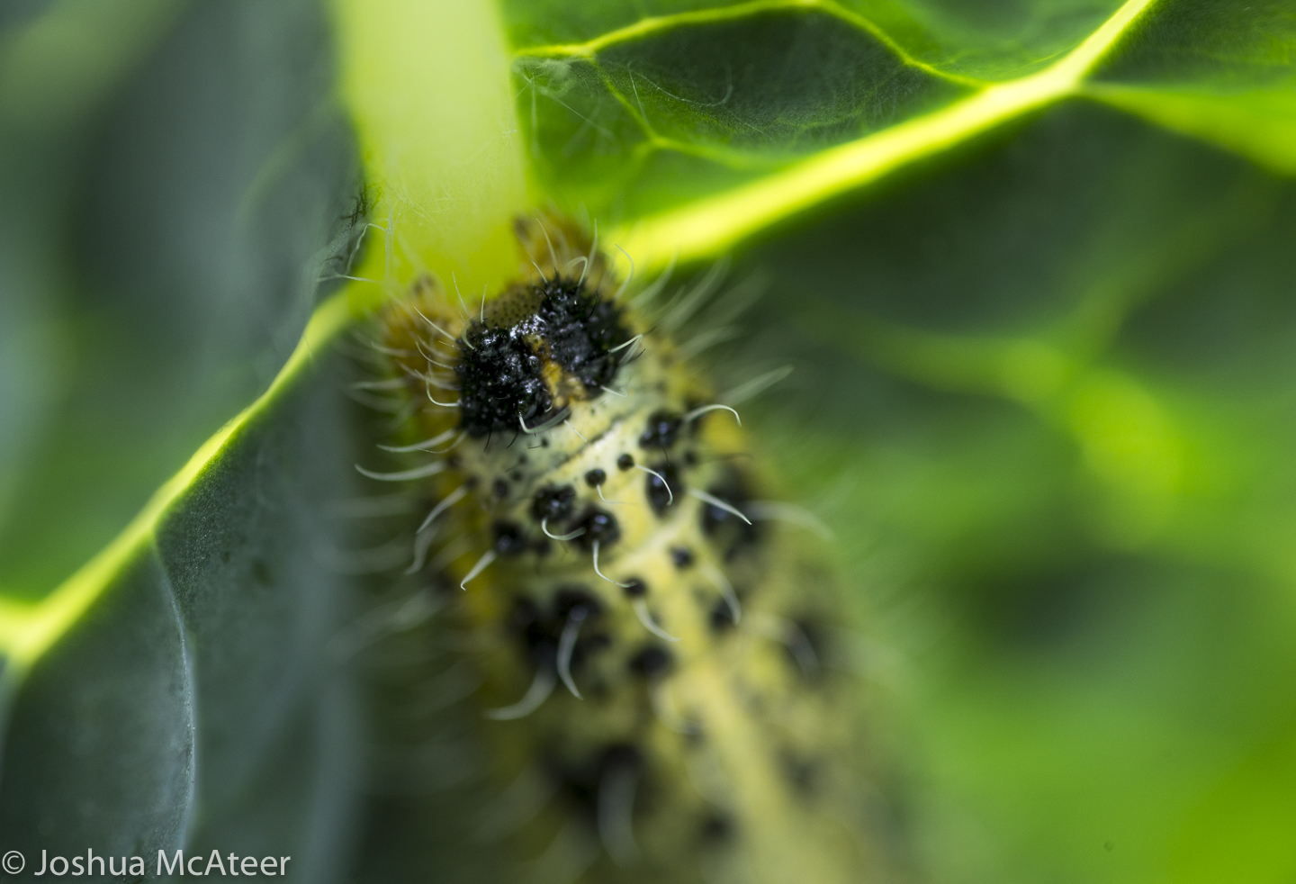
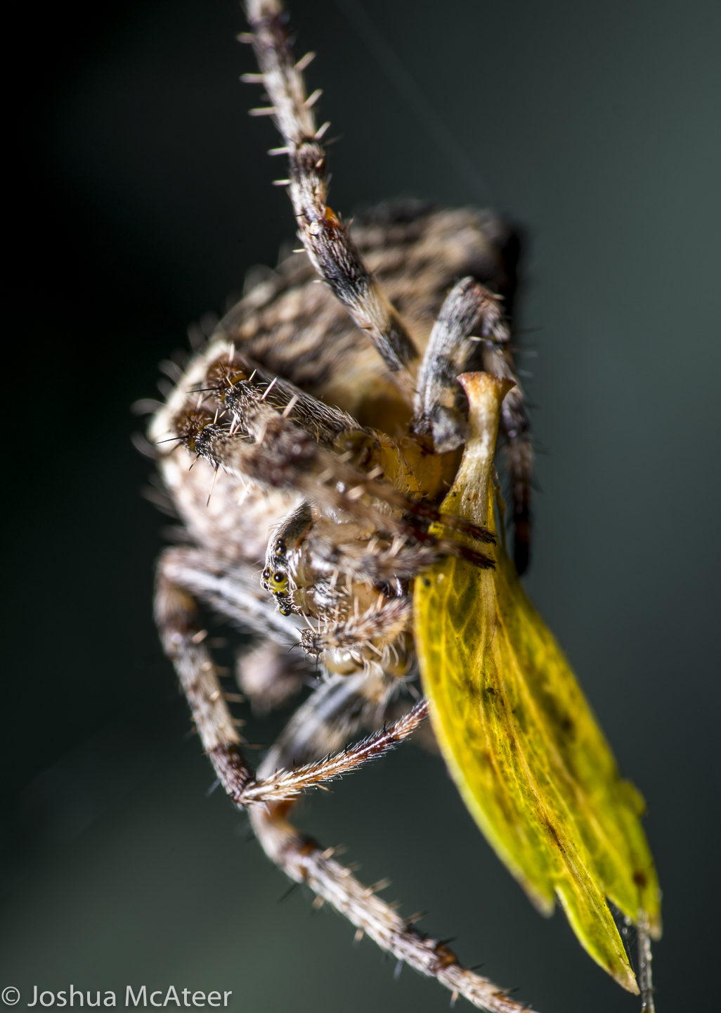
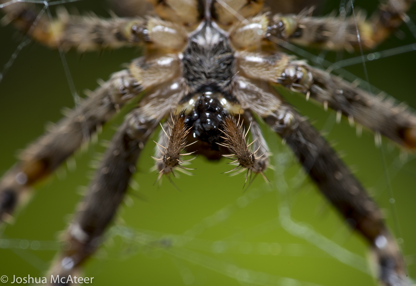
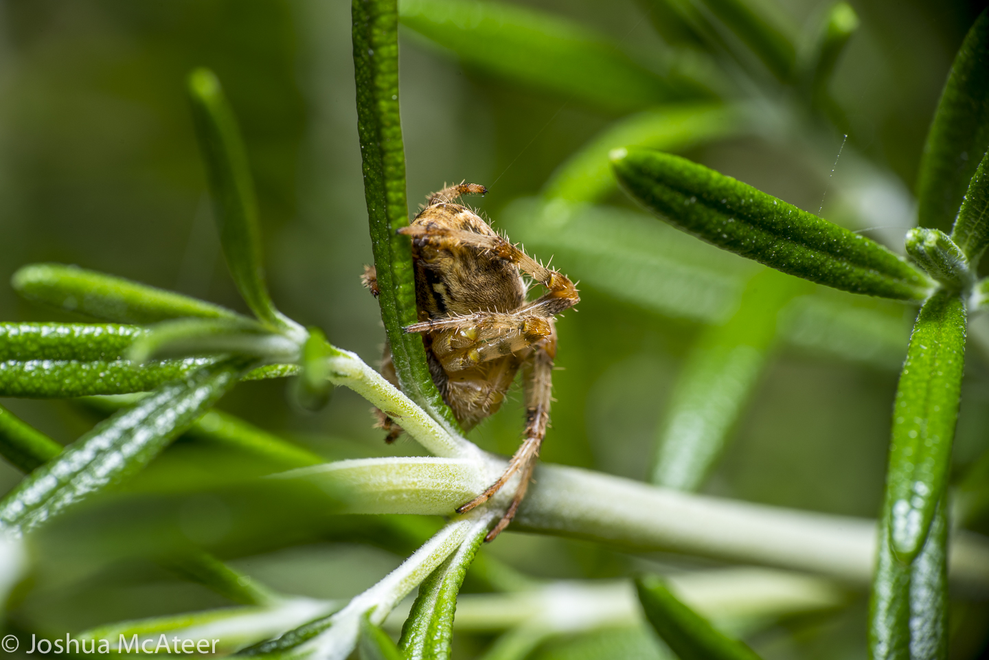
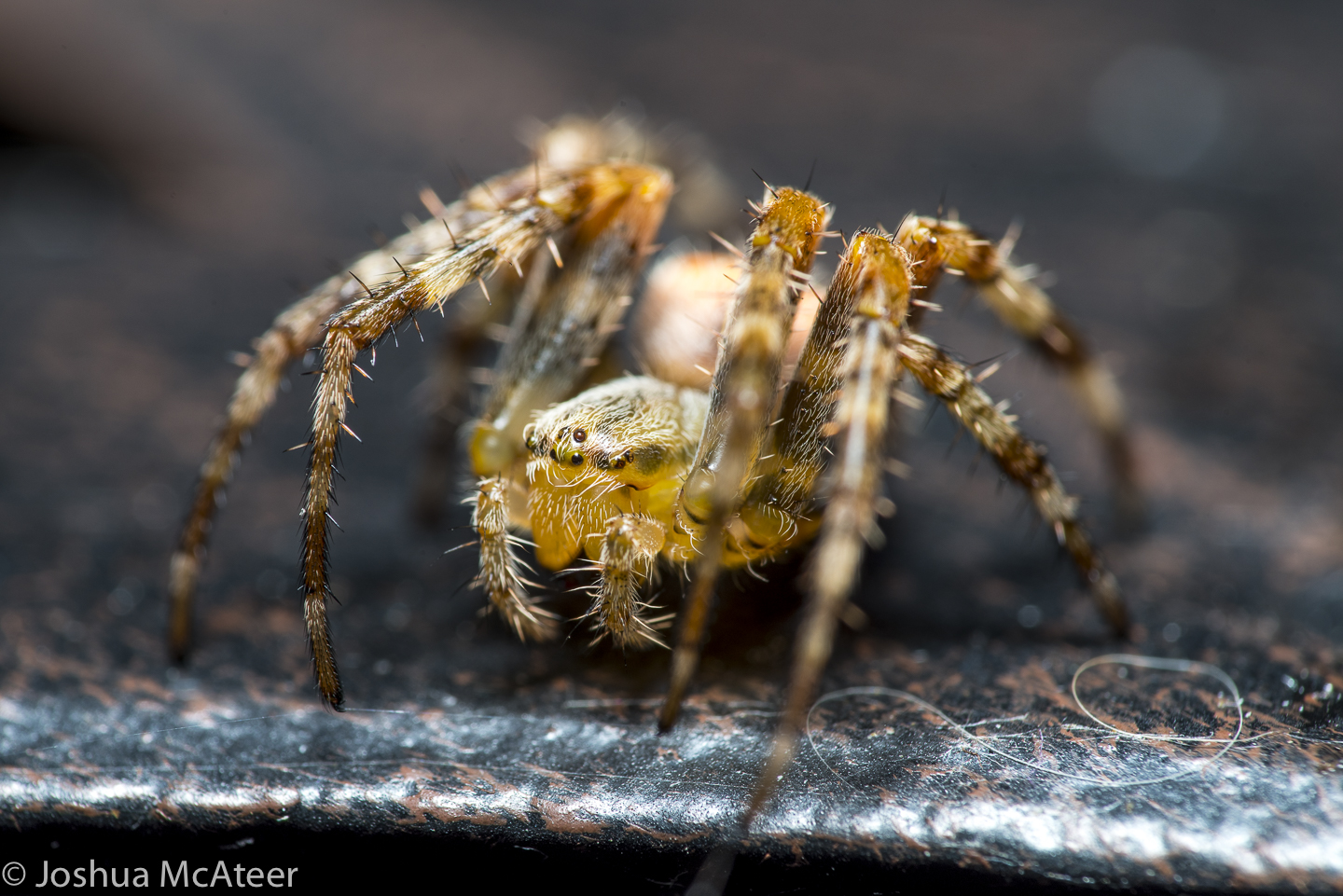
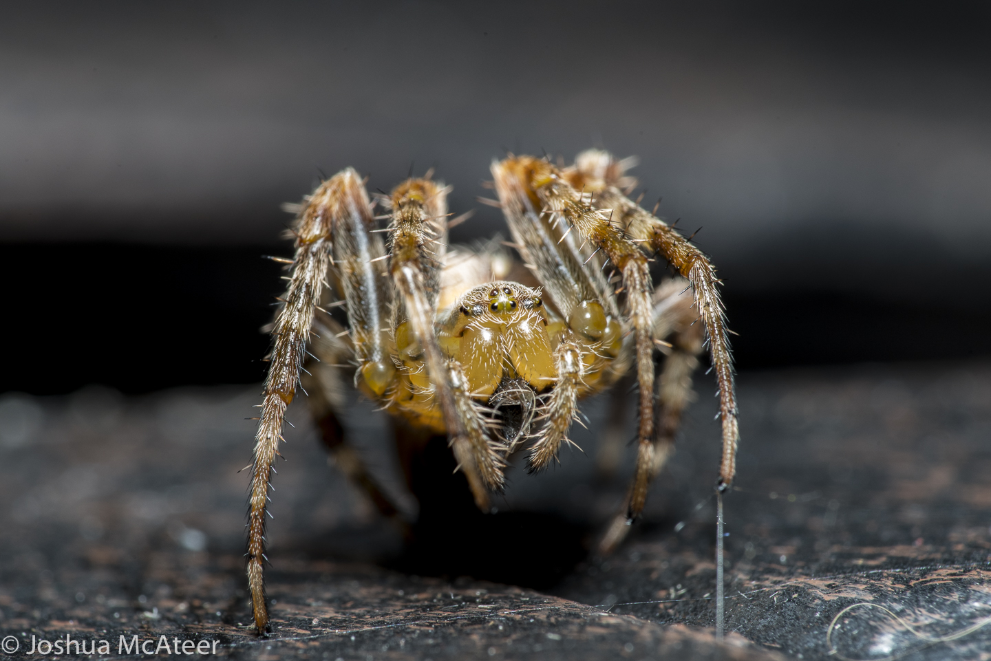
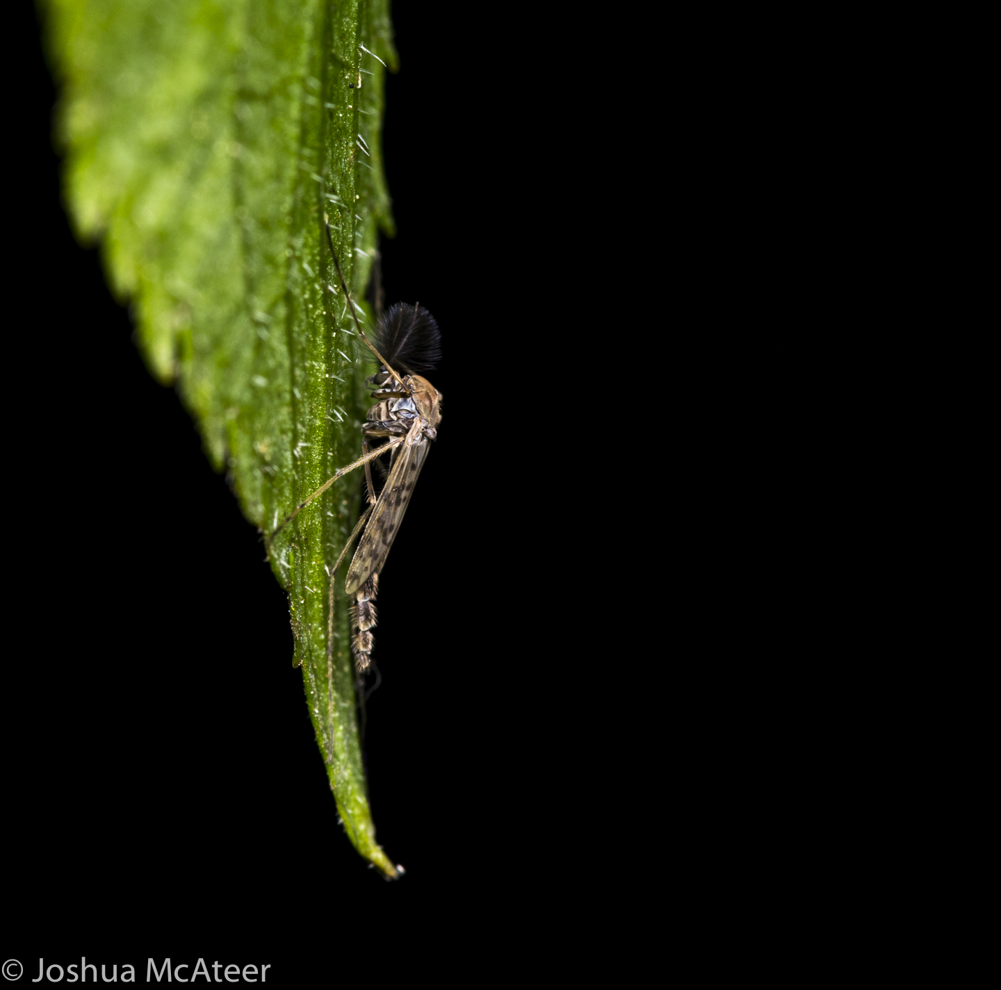
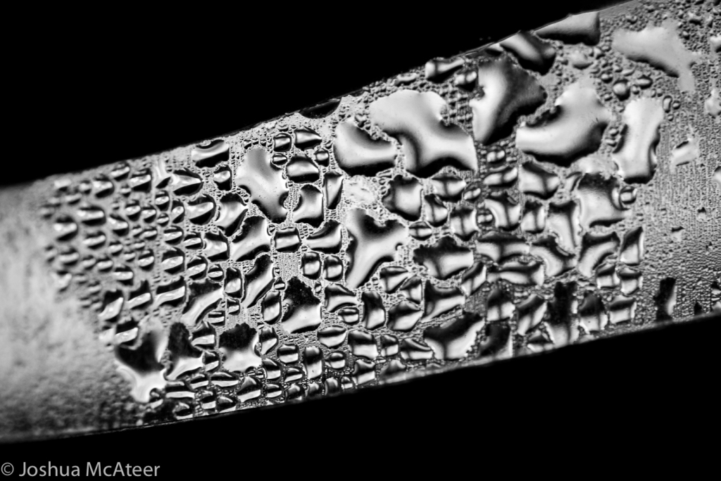
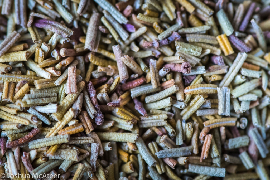
These images were shot in my garden at low magnification using my new Laowa 90mm macro lens. It’s a great lens, apochromatically corrected, super sharp, and with up to 2x reproduction ratio. Here are a few images I captured using it.
These images were single exposures taken with a diffused flash. The diffused flash yields rich warm colours when the white balance is set correctly. It also avoids obvious specular highlights and increases sharpness. It isn’t always the best choice for macro photography, but I do enjoy the depth caused by the light fall off.
A few simple tips to get the best image quality from budget film scanners. Scanning film can be challenging, high quality dedicated scanners are expensive, and even entry level flatbed for film are pretty pricey. My preferred method is to scan film with a macro lens – perhaps I’ll talk about this method at some point in the future – but today I was going to mention some tips for using the basic 35mm film scanner units which are available on ebay/amazon for between £30-£50. These units all seem to be the same or at least very similar: they are powered by USB, scan to SD cards, and claim a resolution of 5Mpx. Maybe a new generation will come out with a higher resolution sensor, but there are plenty of issues with these scanners and the sensor is not the worst of them.
Typical ebay listing for these sorts of units.
A good 5Mpx scan could be sufficient for digitising photos, especially if you don’t currently shoot film and want to digitise family photos from a few decades ago, as it’s likely that the photos where shot on basic point-and-shoot cameras. If you want to squeeze every drop of image quality from your Leica M7 you probably know that a £30 scanner isn’t for you. To be honest, I don’t think these scanner are for anyone, but if you happen to have one you might be able to eke out a little more image quality with this method.
Dust is the enemy of film scanning. Your film should be as clean as you can make it before scanning. Compressed air, or a hand pumped air puffer, can help to clean up your film and so can water (ideally deionised), however you should make sure not to scan your film wet. If you process your own film you’ll know that you can wash it with tap water and even dish soap, however tap water can leave streaks in your film from the minerals in the water (but if you just dropped your wedding photos on the carpet and they are covered in fluff this is probably a reasonable proposition – and you can re-wash your film if needed).
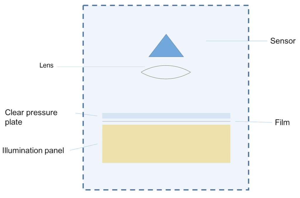
However, with this scanner you don’t need to clean your film at all. This film scanner was sitting in my dad’s computer cupboard for several years before I tried it, and all that time is has been filling up with uncleanable dust. Not only does the design of the scanner make it very likely to collect dust, it also makes sure that all of the dust is visible in your scans. The scanner has a slot from left to right which accepts the film tray, this slot doesn’t have a dust cover, so is constantly collecting dust. Inside the film scanner is a sensor and lens (just like in a digital camera) and a light source and diffuser. When the film is inserted the light source shines through the film. However, as the diffuser for the light source (a sheet of milky plastic) is very close to the film, dust on this sheet will appear in your scan.
If you scan photos with a dSLR you want the light source to be far from your negative so that any dust on the light source is out of focus.
Schematic of these scanner unitsScan from the film scanner without any film. All of this dust is superimposed onto each frame which you scan. Also, you can see that the illumination isn’t even. Scan without any correction appliedScan with dust removal and some simple colour work
The images above were ones which I had processed a few years ago. I thought that I should redo the process with a few intermediate steps to prove to myself that I had remembered all of the steps.
First you need to scan each frame multiple times. I did this two ways, the first was better and the second was faster. The first way is to scan the frame, then wiggle the tray around a little and scan again (you should repeat several times until you have at least 5 scans of each frame). The second method is to scan the whole strip 5 times and just hope that you moved the film holder a little each time.
At the moment you’ll have several images where the dirt is in the same place but the picture moves, we can swap that up so that the picture is in the same place and the dirt moves.
Unregistered images from the scanner. The image moves, but most of the dust stays still.
I found all of the images from the same frame. As you can see the scan area is significantly smaller than the 35mm film frame – another issue with theses scanners. To complicate issues, there are three different kinds of artifact which we want to remove, marks which are fixed in the scanner frame, marks which move a little in the scanner frame, and marks which are on the film. The distinction of marks which move a little in the scanner frame is important as if these didn’t exist we might be able to perform background subtractions, or use the image with no film as a mask to show where the dirt is.
Registered images, for some reason the automatic registration failed.
The registered images show just how much fluff and rubbish is inside the scanner. For a more accurate alignment it is helpful to increase the resolution size (by interpolation), I doubled the number of pixels in each direction, and downsampled the image at the end of this whole process.
Next is where the magic happens. How do we keep the bits which are the same, but remove the bits which move? The median filter! Just as a quick recap, you probably know the median as a centre point estimate, you might use it like the mean if you have outliers in your data. Well, that’s exactly what we have here. Hopefully, if we stack each image on top of one another and look at each pixel we’ll have 5 pixels which are very close in value, and one which is bright white (the dirt is opaque and the negative has the intensity reversed). Now, if we sort the pixels by intensity and the select the one in the centre there is a very good chance our selected value will be close to the true intensity value on the film without the artifact from the dirt.
This process isn’t perfect of course, one issue is that if each image is very dirty then there might be many regions where all of the stacked up pixels happen to be in dirty regions. However, the more images we include the better we can remove the dirt. Also, we will average out noise and JPEG artifacts. For removing noise and JPEG artifacts taking the mean would be slightly more effective, however, for dirty regions which are close to 100% white caused by the dirt we would be left with 6 copies which all have 16.7% brightness all over the image – which might be worse than just one copy of them. Especially if you had to clone-stamp them all out.
The result of the median filter. I did call it a magic trick, but it’s less Wingardium Leviosa, and more ‘Is this your card?’.
The median filter cleaned up the image a lot, but there is still a lot of mess in the frame. Some of this is dirt on the film, or small scratches.
We can easily clone-stamp out the remaining fluff and brighten up the image.
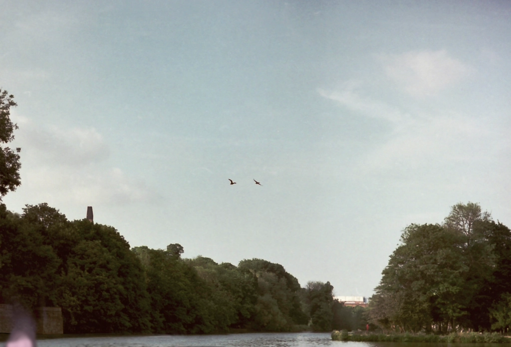
After touching up the image with the clone-stamp and adjusting the brightness we could say that we’ve got the most out of the scanner (and the frame). Zooming in you can the significant noise in the sky, and the halos around the birds caused by the sharpening algorithm in the scanner.
This film cost £1 (it’s Agfa Vista 200) and if you can’t see the grain in £1 colour film then there is probably something pretty bad going on in the scanning.
So, what are your scanning tips? Do you have one of theses scanners? Do you think you’ll use this technique?
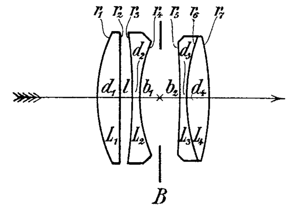
In April 1902 Paul Rudolph, of the Carl Zeiss firm, applied for a patent for a camera or projection lens:
Lens layout from US patent 721240A
‘[Constructed by]… arranging four single lenses in two groups separated by the diaphragm, the two components of one of the groups inclosing an air-space between their two surfaces, facing one another, while the two components of the other group are joined in a cemented surface, and the pair of facing surfaces having a negative power…’
The full specification of the lens is included in the patent, but the wording is extremely broad. The Tessar is considered to be any lens of four elements, with a doublet and a pair of singlets. However, Rudolf Kingslake in The fundamentals of lens design gives more insight, describing them as like Protars but with an air-spaced front group, the Protar being another design from Rudolph and produced by Zeiss from 1890.
Lens formula from US patent 721240A
If we want to swap out those refractive index values for Abbe values we can simply fit Cauchy’s equation and use that to estimate the C-line index, giving the table below.
Simply fit the three wavelength/index pairs to Cauchy’s equation to calculate the missing values. Only the first two terms were needed.
nd (589.3nm)
Vd
∆P(g,f)
Lens 1
1.61132
58.4128
0.020117
Lens 2
1.60457
43.2243
0.012310
Lens 3
1.52110
51.5109
0.013207
Lens 4
1.61132
56.3675
0.021767
Refractive index Abbe number and anomalous partial dispersion for the glasses listed in the Tessar Patent
The original patent lists most of the values needed to model and construct the lens, however, you might struggle to find those particular glasses. A more modern formulation, from Kingslake, would find the same basic lens updated with modern (for 1978 in the case of my copy of lens design fundamentals) glasses, SK-3, LF-1, and KF-3, of note is the significant decrease in index of the second lens, but still flowing the same idea of a dense crown for the outer elements and medium flint for the second, and a light flint for the third.
The system focal length seems to be nominally 1000mm and back focal distance is 907mm. For the purposes of this exercise the presented designs will be scaled to exactly 1000mm focal length.
The lens produces an image circle of approximately 500mm. Requiring good performance over this size field is a challenge, but would be necessary if the camera was intended to be used without an enlarger. However, if only contact printing was intended then the definition requirement would be significantly lower. If the camera was to be used with wetplates then the chromatic aberration requirements become quite challenging, as the camera needs to be corrected for longitudinal chromatic aberration in the visible light (where it is focused) and the near-UV where most of the exposure comes from.
My initial hope/plan was to simply re-optimise this lens with modern computer optimisation and to get a slightly better performing lens at f/4 over the f/5.5 lens. This did not happen. It seems that Zeiss’s reputation was well earned. However, what I did do was significantly alter the lenses character and learn a lot on the way. For one, I didn’t really understand the importance of vignetting for aberration control, as you can clip off some of the problematic rays near the edge of the field of view, with only a small loss in edge illumination.
We can assess the performance of a photographic lens in a number of ways. From a design point of view one of the most obvious is spot size. This is the size that a single point of light would make at the focus of the lens. Different object distances can be considered, but for this I only looked at objects at infinity. Lenses tend to have better definition in the centre than at the edge, so it is important to examine the spot size at different field angles. Also, since lenses have dispersion it is important to also examine the effect of wavelength on the system. I used three main methods to judge image quality, the polychromatic spot size, chromatic focal shift, and image simulation. The image simulation also gives an idea of the performance of the whole system, including sharpness, chromatic aberration, and vignetting.
Layout of the Patent version of the Tessar, at f/5.5.Raytrace of the Patent Tessar, at f/5.5.Chromatic focal shift in the Patent Tessar. The maximum focal shift is 916µmSpot diagram for the patent Tessar at 0˚, 7.5˚, 15˚, 20,˚ and 30˚ at f/5.5. The colours show the wavelength.
There are some things we do know about the lens such as properties of the glass and the radii of the curvatures. But there is also other information which we don’t know, such as the semi-diameters of the lenses, or the manufacturing tolerances of the system. If we guess at the first and ignore the second we can model the system as shown in the figures. The rear lens group is slightly smaller than the front group, vignetting some of the rays – this is set by the edge thickness of the rear lens.
To characterise this lens we might say that it is well optimised over the whole field, with the spot size increasing by more than a factor of 3 from the centre to the edge. The chromatic shift isn’t significant and at f/5.5 there isn’t any obvious lateral chromatic aberration.
I re-optimised the lens several times, tweaking the weightings of various factors. I decided that distortion wasn’t an issue, and that over-all central performance was more important the edge or the very centre. I also kept the same glass as the original. The prescription which I arrived at is
Radii/mm
Thickness/mm
r1
213.366
L1
40.881
r2
-3276.842
gap
19.710
r3
-648.011
L2
11.081
r4
197.148
to stop
39.115
r5
-777.429
from stop
19.649
r6
221.080
L3
8.382
r7
-340.573
L4
46.140
Backfocus
887.795
Re-optimised prescription for lens
Re-optimised lens layout at f/4
As can be seen from the table and the layout diagram the first lens of the re-optimised lens is almost unchanged. The second lens is slightly strengthened on both surfaces. The rear doublet is thickened and has more power. This might have been avoided in 1902 due to the cost of the ‘new achromat’ glass. Overall, the lens is not much changed, at least by examination. I expect that the 1902 patent lens would be less expensive to make due to the weaker surfaces and thinner lenses. However, in the re-optimisetion I did squeeze an extra stop of speed out of the system.
Raytrace of the re-optimised Tessar at f/4Focal shift in the re-optimised Tessar, maximum focal shift is 766µmSpot diagram for the re-optimised Tessar at 0˚, 7.5˚, 15˚, 20,˚ and 30˚ at f/4. The colours show the wavelength.
The re-optimised Tessar is a slightly better achromat with a smaller maximum chromatic focal shift of 766µm instead of the 916µm of the original Tessar. This is probably not significant. I don’t know exactly how the original lens was achromatised, however, my choice was to achromatise 0.54µm and 0.4861µm. These value were chosen as they are close to the peak sensitivity of the eye and of the collodion process, hopefully, a photographer could focus in the visible light and expose with minimal focus shift in the blue/near UV.
In the spot diagrams of the re-optimised lens you can see an obvious design choice, the centre spot has been allowed to increase in size slightly, and the very edge spot has increased significantly, all of the other regions show significant spot size decreases. This is due to a difference how I would personally like to compose images, with a less strong centre bias than 1902-Zeiss expected.
The average spot size for the re-optimised lens is significantly larger than for the patented example although almost all of that is in the very edge, but we can’t judge it too harshly as the re-optimised version is almost a stop faster at f/4 rather than f/5.5. If we stop it down to f/5.5 we get a slightly different result.
Raytrace for the re-optimised Tessar, at f/5.5.Spot diagram for the re-optimised Tessar at 0˚, 7.5˚, 15˚, 20,˚ and 30˚ at f/5.5. The colours show the wavelength.
The spots have decreased significantly over the field when stopped down, as would be expected. The central spot size is now almost the same as in the patent design, and the 15˚ spot size is now smaller than the 7.5˚ spot size in the patent design – this significantly increases the region of good definition of the system.
Perhaps a more meaningful way of comparing the lenses is by simulating an image made from them.
Comparison of the image quality between the original patented Tessar and an re-optimised version of the lens.
Examining the simulated image (which doesn’t take into account depth) we can see some of the character of each lens. Like with any other artistic tool, the final judgement is based on the desired use.
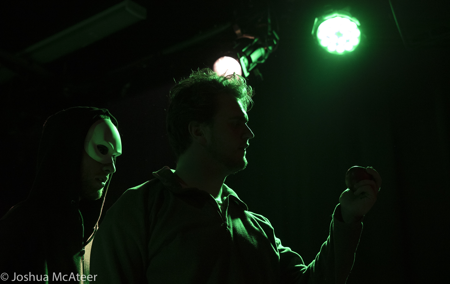
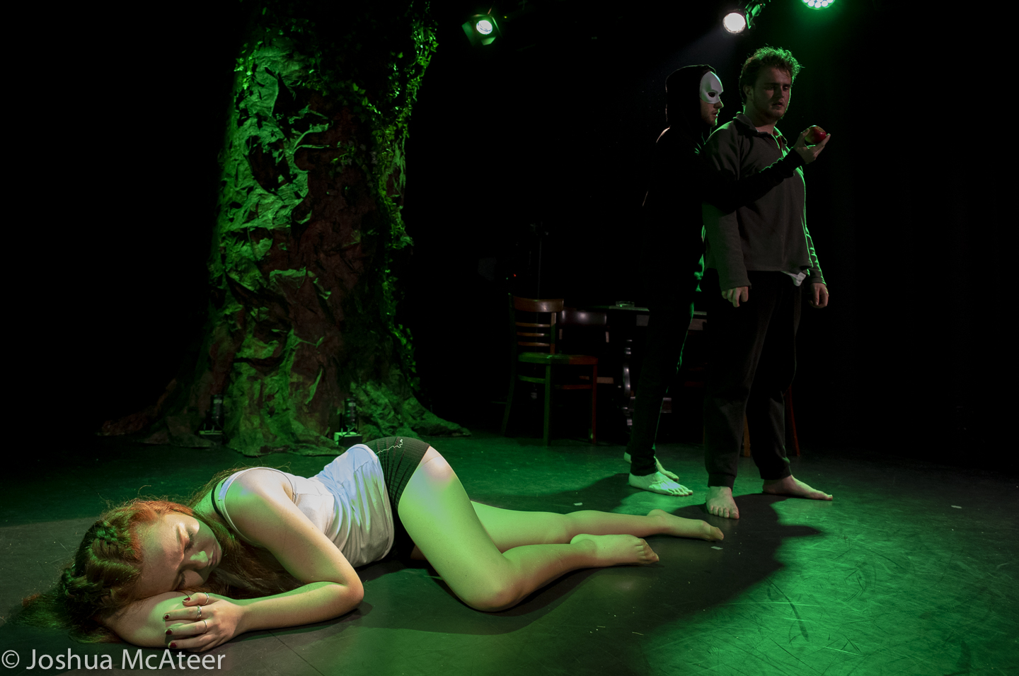
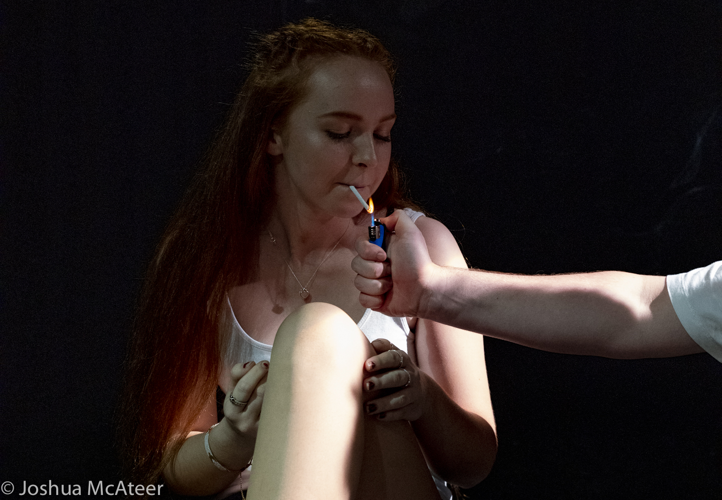
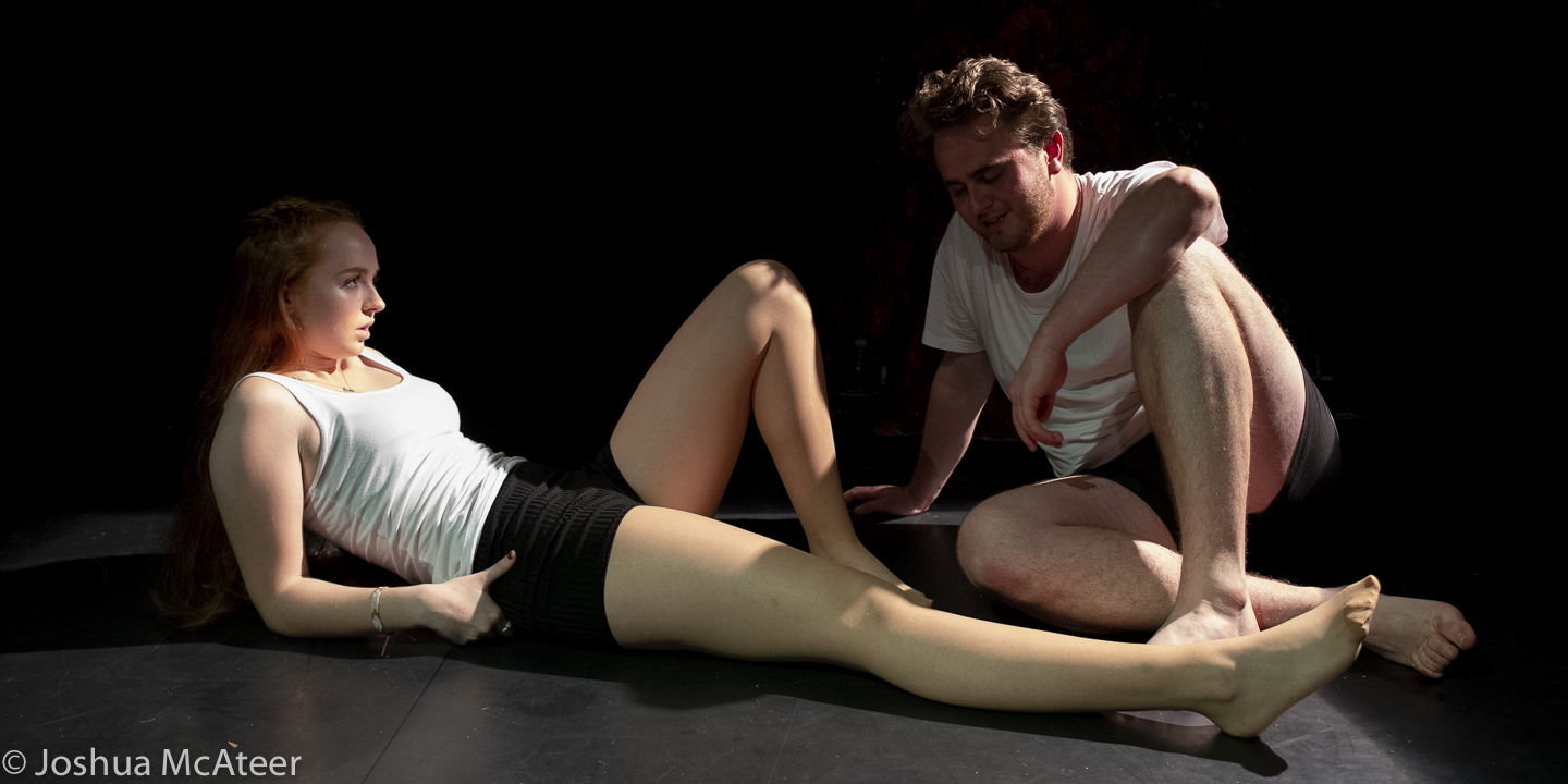
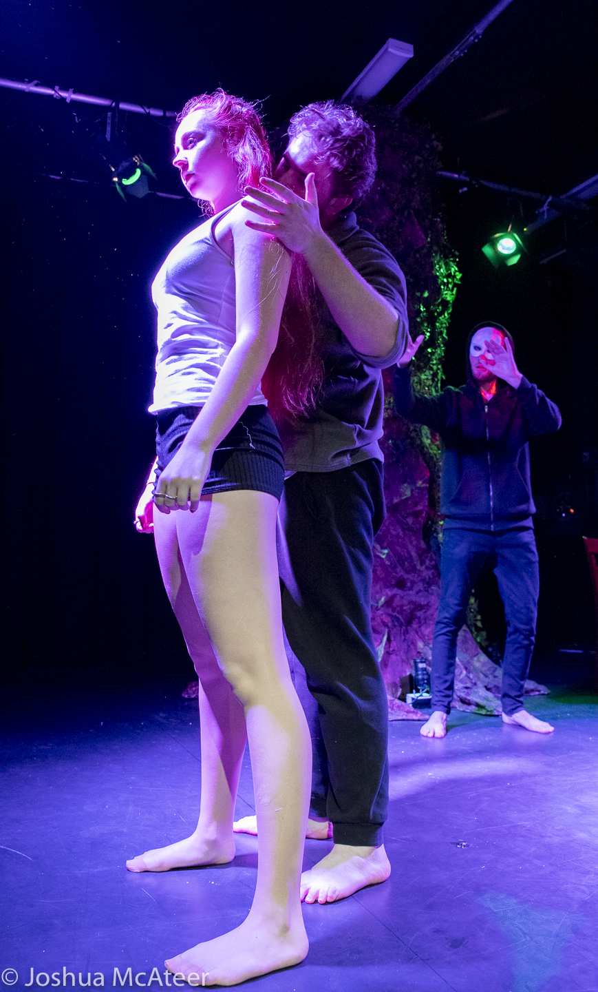
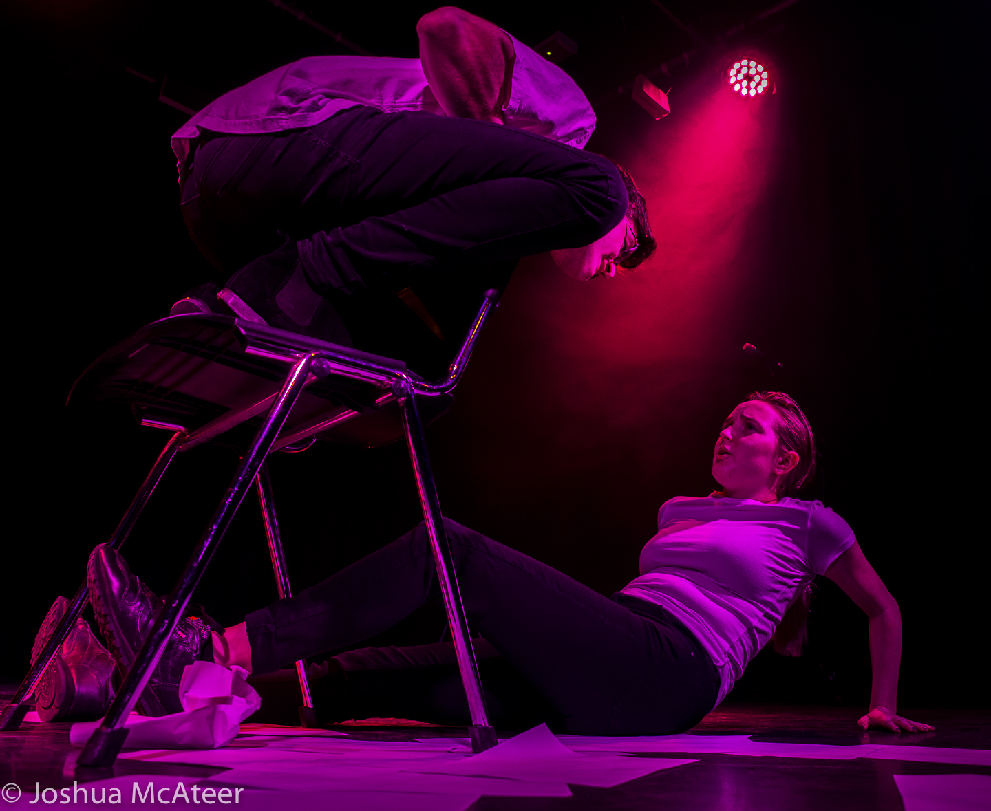
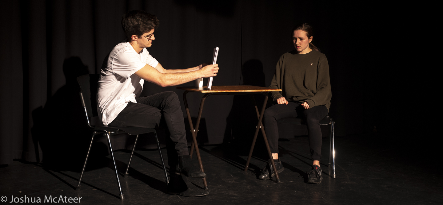
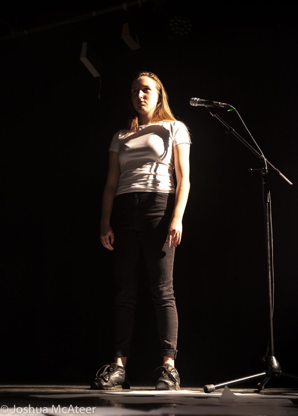
On Saturday I did the production shots for Adam and Eve, a production put on by Tara Anegada. The show was excellent from the acting to the set and lighting. Some more information about the show is available on https://history.newtheatre.org.uk/years/18_19/eve_and_adam/
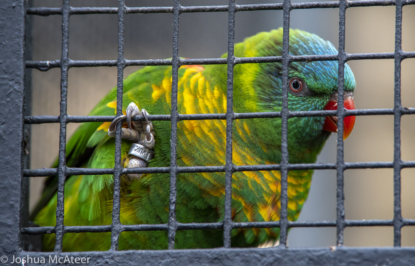
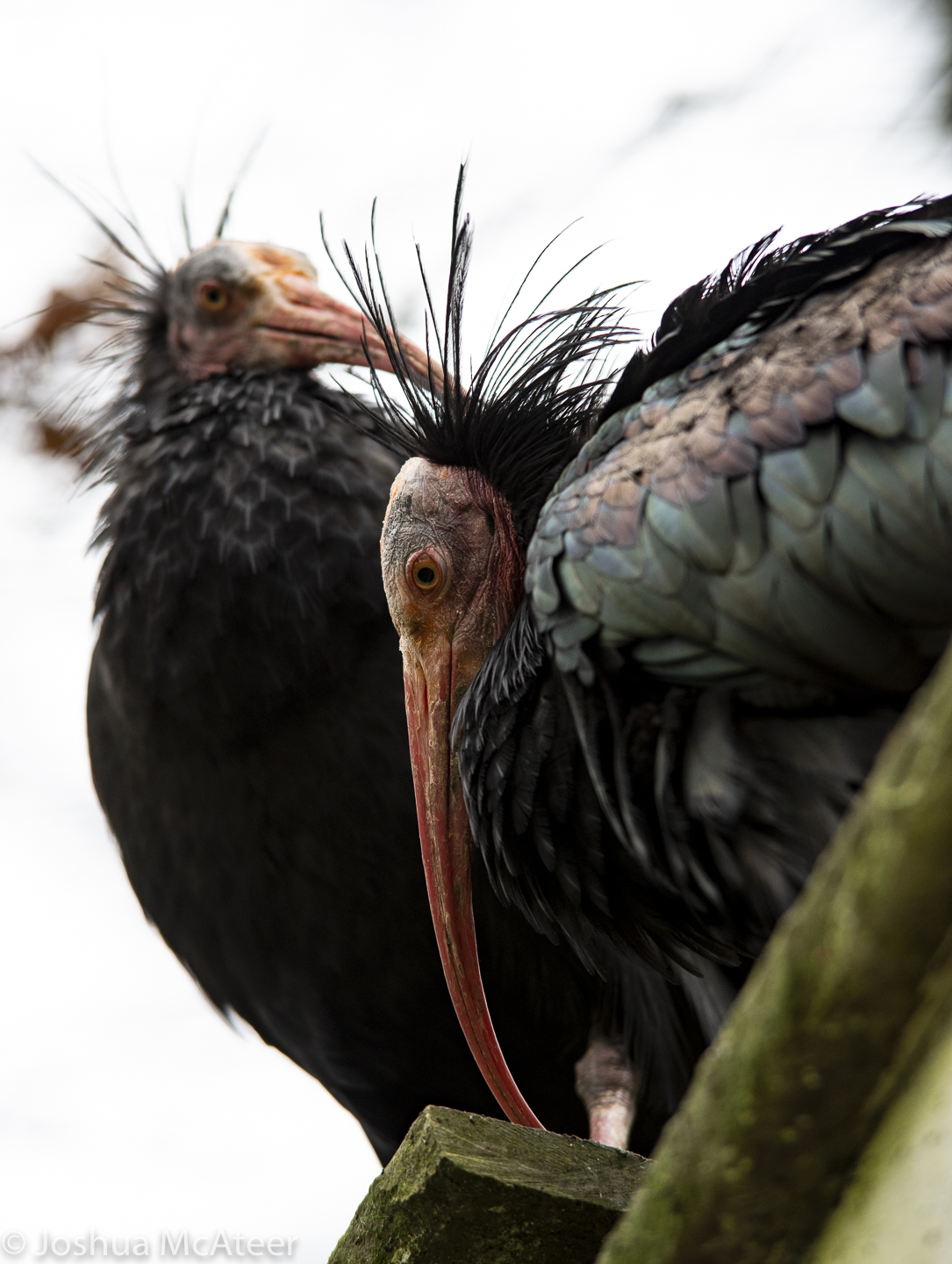
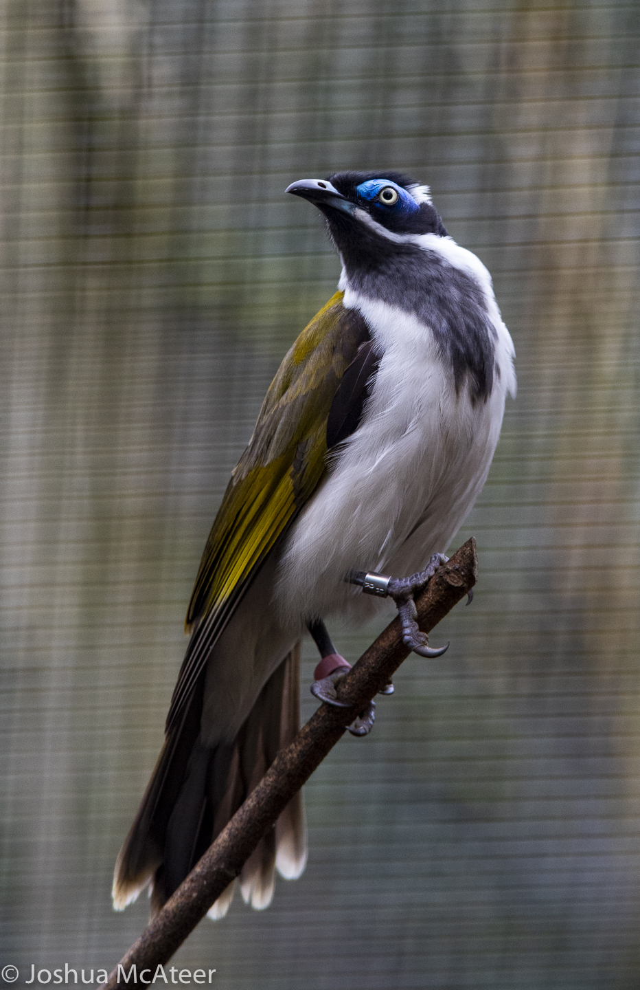
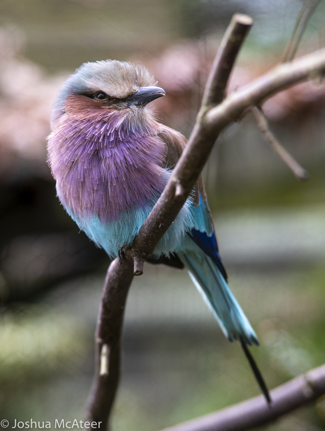
Over Christmas two photography related events happened. I acquired a 70-200, and I also went to Birdworld. These are some of the results. I really liked the lens (an older tamron) it’s quick to focus and brilliantly sharp at f4. The screw af is quite loud though and swapping between manual and autofocus is slow on pentax cameras.
My keep rate was about 7% for this outing, which is pretty good for me. Hopefully, as I become better acquainted with the lens that’ll go up.
The focus on the lens is a little slower than my SDM lens. But it is still snappy. I found that, to nail focus on the exact part of the eye I wanted, I needed to manual focus when the scene had foreground elements such as mesh or fence – which is completely normal.
On Sunday I photographed the dress rehearsal of Heather, by the Nottingham New Theatre. The play was written by Thomas Eccleshare, and directed by Tara Phillips. The entirely student-run, theatre put together an excellent performance. From the acting to the technical effects.
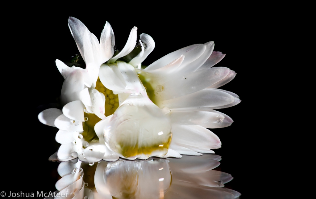
I had a specific idea in mind for this collection of photographs, an idea which I will be expanding on in the future. These are all set up single light images which have been focus stacked. I almost really like the last of these images with the daisy. However I can’t get it to look quite right. There is a reason it is called filename-Edit-edit-3.tif.
Theses shots were all taken with a studio flash head and a manual macro rail. Adjusting the focus, waiting for the vibrations to stop, taking a photo, adjusting the focus… takes a long time. I’ve since built an automated focusing rail which is much more accurate and leaves me free to make a cup of tea.
The depth of focus in macrophoto is tiny. It is even narrower when using a microscope. In microscopy ‘optical sectioning’ is a vital tool in resolving 3D structure. However, in macrophotography we often want to take front-to-back pin-sharp images. For this, we take hundreds of photos, align them, and merge them so that only the in focus details are included. Luckily, there is software for this, but if you look at the photo of the daisy up close, you’ll see how this can go badly wrong.
Tiny animals are amazing. Their whole bodies can be thousands of times smaller than our brains, yet they can move, breathe, reproduce and hunt or forage successfully and have done for millions of years. On this small scale animals work in unfamiliar ways. Many animals have exoskeletons made of chitin, and move their limbs through processes which are much more similar to hydraulic excavators than our paired muscle systems.
Our tiny friends are immensely strong and fast. Arthropods are an incredibly diverse set of animals, and they they share their tiny world many other fascinating creatures.
I recently read a very readable book called animal eyes by Dan-Eric Nilsson and Michael Land, it goes into a satisfying level of detail in how the eyes of sea creatures, arthropods, mammals, birds and historical creatures function and how that function effects how they interact with their worlds. As someone who is very interesting in optics and cameras, it is very interesting to learn more about who to design optics by random mutation, although perhaps Pentax and Nikon should stick to paying engineers.
Here is a small collection of photographs from Highfields park. These were taken with a Pentax 100mm f/2.8 macro lens and a diffused flash.
Some people take in-field macro shots on a tripod. I’m not really a fan of this and the insects often move about quickly. That’s why I use a flash. Flashes dump almost all of their energy in about 1/2000th of a second, or faster. It’s really hard to get sharp hand-held macro shots without one. To blur the image by less than ten pixels at 2x magnification I’d only be able to move 20 microns. This is easy in 1/2000th of a second, but in 1/40th of a second I’d have to make sure I move at less than 0.8 mm/sec.
These were all taken with a Pentax 100mm f/2.8 macro, it’s an excellent lens. Some of the images were taken with a Raynox DCR-150 close up lens. Off-camera flash was also used.
Macrophotography is amazing. The most mundane scenes can appear totally alien even at only low magnification. It might surprise you, but the smallest details which we can see unaided eyes is around 0.04mm, and that’s when you hold things right up close. These images have a resolution of about 2-4 microns (0.004mm) so ten times better. Also, they are still, well-lit, and have had the colours and contrast edited so that they look more pleasing.